Hi all,
I put this together for something else, but I thought I’d post it here in case it’s useful for anyone. I know people can sometimes get a bit confused wiring up stomp boxes, so I’ve tried to explain it as best as possible (if you notice any errors, please let me know).
How to wire up a Stomp Box / Effects Pedal
Apart from the effects circuit itself, there are three things that have to be thought about when wiring up a stomp box, which are the stomp switch, the stereo input jack and the DC-in connector.
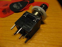
I’ll be referring to this image throughout the explanation.

The Switch
In the OFF position, pin 4 is connected to pin 1, pin 5 is connected to pin 2, and pin 6 is connected to pin 3 (in my diagram at least – you may have a switch with different numbers written on it).
To try to make this easy to follow, consider the left-hand column of the switch to be the input column, the middle column to be the output column, and the right-hand column to be the LED column.
Looking at just the left and middle columns, the input comes in on the yellow wire to pin 4, is directed upwards to pin 1, which is shorted to pin 2 via the blue wire, then this is redirected down to pin 5 which is the output (brown) wire. In other words, a bypass is in operation. As the effects circuit itself is completely disconnected, it cannot influence the signal, so this is true bypass.
As for the right-hand column, there is not much going on there. The earth is connected to pin 6 via the black wire, but it is not redirected anywhere, so nothing happens, and the LED does not light up.
Now in the ON position, pin 4 is connected to pin 7, pin 5 is connected to pin 8 and pin 6 is connected to pin 9.
Again, looking at just the left and middle columns, the input comes in on the yellow wire to pin 4, is directed downwards to pin 7, which then goes to the input of the effects circuit via the green wire. The output of the effects circuit goes to pin 8 via the purple wire, and this is redirected up to pin 5 which is the output (brown) wire.
As for the right-hand column, the earth is connected to pin 6 via the black wire, which is redirected down to pin 9 and fed to the negative terminal of the LED, allowing it to light up.
OK, that’s the switch explained, but there’s more going on here.
The Stereo Input Jack
You may be wondering why a stereo input jack is required, when you are only using a mono signal. Well, that’s because the third connector (pin 3) on the input jack is used to control the power supply to the circuit.
Let’s assume for a moment that you are using a battery. Instead of the negative of the battery being connected straight to the negative of the effects circuit, which would mean the battery is in use ALWAYS (even when the circuit appears to be switched off), the negative of the battery is instead connected to the third connector (pin 3) of the stereo input jack. That way, when nothing is plugged into the stomp box, the third connector is not connected to anything and the battery is not being used. When you plug in a mono jack plug, it shorts the third connector to the shield connector (pin 1) of the socket, which in turn connects it to earth, powering the effects circuit.
You may wonder why you don’t just power up the battery at the same time as switching on the effects circuit. Without going into too many details, this is because the sudden surge of power leads to a loud popping noise, which no-one wants to hear.
The DC-in Connector
Lastly, we have the DC-in connector. This also has three connectors and can sometimes cause confusion, since instead of having a positive inner (centre pin), it actually has a negative inner. I’ve numbered the pins in the diagram for clarity, as follows: pin 1 is the (negative) inner and is connected to the negative of the battery, pin 2 is the outer and is connected to the positive (+9v) of the effects circuit, and finally in a similar way to the stereo input jack, pin three is the 3rd, extra, pin and is connected to the positive terminal of the battery.
(The difference between this and the input jack is that in this case, pins 2 and 3 are normally shorted UNTIL you plug in a power supply, at which time pin 3 becomes disconnected.)
When nothing is plugged in, the positive terminal of the battery, which is connected to pin 3, is shorted to pin 2, and continues on its way to the positive of the effects circuit. When the power supply is plugged in, however, pin 3 (and therefore the positive of the battery) is disconnected, and the positive voltage from the power supply goes directly to the effects circuit via pin 2.


 [/quote]